BROC U | Issue #10 | Downtime for an Athletic Facility Can Be Crippling, Limit it Through Some Easy Identification
The Problem
Consistently we find ourselves receiving requests for items that many people just don’t know the name of or how to explain. Rather than having to pay to have a service technician make a site visit, we have put together a small cheat sheet for those situations.
Many times, there is a consistent process that involves a lot of back and forth and site visits that really slow the process of rectifying an issue. A preferable and less downtime effort involves becoming more familiar with the parts or mechanisms that make up the equipment.
The Solution
We have devised a small map of information that could be helpful for people to understand the name and use of specific pieces of their equipment. Frankly, this is a safety tip in of itself, learning more about the equipment that is operated inside your facilities makes it so that you are more aware of the potential issues that may arise. In turn this should help expedite the issue to a solution on how to address the problem and certainly in those necessary cases, explain to potential service technicians what is occurring and where.
Limit Your Downtime
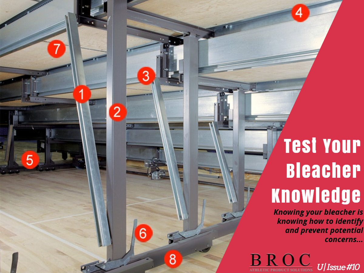
For many people, downtime in a busy sports facility is a number one concern in making things flow smoothly. Gone are the days of laid back nature and moving schedules with ease. So many things are occurring and schedules in those facilities are tight, so this is made to help minimize any potential downtime and expedite things back to their working state. The following maps parts back to an exact image that replicates many of the systems inside facilities today:
1 – Stabilized by Sway Braces
All Interkal seating systems are stabilized by sway braces attached to the vertical columns and steel risers for maximum strength and resistance to movement. (Sway braces not required on rows 1 and 2).
Sway braces fabricated from steel are essential for vertical post bleachers to resist the compression and tension forces created when the bleachers are loaded.
2 – Structural Steel Tubing
Electric-welded continuous 2”x3” closed seam, rectangular structural steel tubing produces the strongest and safest vertical columns. Post size increases depending on row height and load bearing requirements.
3 – Deck Support Brackets
Deck support brackets are more rigid than competitive designs to help prevent sagging and potential binding during operation. All deck supports incorporate rollers for efficient operation and deck stability.
4 – Nosebeam Construction
Nosebeam Construction – All Interkal seating options incorporate a structural continuous galvanized nosebeam to which the seat surface is attached, resulting in a uniform understructure. This component provides superior strength, continuous support for the plywood deck and the flexibility to achieve any aisle location/configuration.
5 – Superslide System
Superslide System – Low friction flexible rod system guarantees positive engagement of vertical supports without binding, assuring smooth operation over uneven floor conditions.
- Maintains proper vertical column spacing.
- Reduces wear and helps eliminate racking damage.
6 – Row Locks
Row Locks – Stabilize the bleacher under load in the extended position by securely locking each support post to an adjacent post.
- Automatically engage and release for opening and closing operation.
- Individual row locks make it possible to open any number of rows without opening the entire bank of bleachers.
7 – Aluminum “H” Beams
One-Piece Wheel Channels – accommodate 8 to 12 wheels per row for maximum weight distribution and operating ease. The number of wheels increase as the number of rows increase.
8 – One-Piece Wheel Channels
Aluminum “H” Beam located at every plywood joint provides continuous support from rear riser to nosebeam. Also facilitates ease of cleaning by eliminating unsightly gaps.
- Wheel channels are precision formed from a single piece of steel coil for maximum rigidity.
- The heavy-duty composition rubber wheels are provided in a 3-1/2” diameter by 1-1/8” tread width. This increased tread width allows for increased distribution of loads to the flooring surface.
- All wheels are provided with a 1/2” diameter steel axle secured with tamper-proof retaining rings.
- Wheels are equipped with oil impregnated sintered metal bearings to assure smooth operation.
All these parts remain critical pieces to make the system operate smoothly. Knowing the basics of their purpose, operation and makeup could help improve how you manage your facility maintenance today and into the future. We have found after having put hundreds if not thousands of individuals through training on safety inspection procedures and maintenance programs, it is clear the improvement in making problems less impactful to the facility and limiting downtime in some cases by over 50% when problems arise. We are here to help, so help us help you – make a call to our office at 303-973-4517, if perhaps there are items that just need a little bit more clarification.


